


Pressure drop in filtration systems: causes, calculations and solutions
In any industrial filtration system, pressure drop is one of the most critical parameters to monitor and manage. Whether you are operating a simple bag filter or a complex multi-stage filtration setup, understanding filtration pressure drop helps you optimise performance, reduce energy costs and prevent unexpected downtime. This article explains what pressure drop is, what causes it, how to calculate it, and most importantly how to solve it.
What is pressure drop in filtration?
Pressure drop (often written as ΔP) is the difference in pressure between the inlet and outlet of a filter. In other words, it is the energy a fluid “loses” as it is forced through a filter element or housing. Every filtration system experiences some degree of pressure drop; it is a natural consequence of the resistance the filter medium creates.
A low pressure drop indicates a clean, well-functioning filter. A high pressure drop signals that the filter element is clogged, undersized or incorrectly selected for the application.
What causes pressure drop in filtration systems?
Understanding the root causes of filter pressure drop in industrial applications is the first step towards controlling it. The most common causes include:
1. Filter element clogging
As particles accumulate on or within the filter medium, the available flow area decreases. This is the most common cause of rising pressure drop in operational systems. Over time, even well-designed filters will experience increasing ΔP as the element loads up with contaminants.
2. Incorrect filter selection
Choosing a filter with too small an active surface area or too fine a micron rating for the application will result in excessive resistance from the very first moment of operation. This is a design-stage mistake that leads to high energy consumption and frequent filter changes.
3. High flow rate
The higher the volumetric flow rate through a filter, the higher the pressure drop. Forcing more fluid through the same filter element increases velocity and turbulence, both of which drive up ΔP.
4. Fluid viscosity
More viscous fluids such as oils, polymers or cold process water experience significantly higher resistance when passing through a filter medium. Pressure drop increases proportionally with viscosity.
5. Filter medium characteristics
The pore size, thickness and structure of the filter medium all influence resistance. Depth filters, membrane filters and surface filters each exhibit different pressure drop profiles.
6. System design and piping
Sharp bends, undersized piping, sudden contractions and poorly designed housings all add to the overall pressure loss in a filtration system, even before the fluid reaches the filter element itself.
Filtration pressure drop calculation
Accurately calculating pressure drop before commissioning a system avoids costly problems later. While exact calculations depend on the specific filter type and application, the general relationship for filtration pressure drop calculation follows Darcy’s law for porous media:
ΔP = μ × Q × R
Where:
- ΔP = Pressure drop (Pa or bar)
- μ = Dynamic viscosity of the fluid (Pa·s)
- Q = Flow rate (m³/s)
- R = Filter resistance (m⁻¹), dependent on the filter medium and contamination load
For practical industrial use, filter manufacturers provide empirical pressure drop curves (ΔP vs. flow rate) for clean filter elements at a reference viscosity. These curves should always be used as a starting point for system design.
Key factors to include in your calculation:
- Clean filter ΔP at design flow rate
- Estimated ΔP increase over the service interval (as the filter loads with dirt)
- Safety margin (typically 20 to 30%) for unexpected peak flows or higher contamination
- Pipe and housing losses upstream and downstream of the filter
A common rule of thumb in industrial filtration is to plan for a maximum allowable ΔP of 0.5 to 1.0 bar across the filter element before scheduling a change or backwash cycle. Exceeding this range risks damaging the filter medium or starving downstream equipment.
What Is an acceptable pressure drop?
There is no single universal answer; acceptable pressure drop in filtration depends heavily on the application and system design. However, the following general benchmarks apply across many industries:
| Application | Typical Clean ΔP | Maximum Operational ΔP |
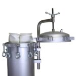
| Bag filter housing | 0.05 – 0.15 bar | 0.5 – 1.0 bar |
| Basket strainer | 0.02 – 0.08 bar | 0.3 – 0.5 bar |
| Multi-bag filter | 0.05 – 0.20 bar | 0.8 – 1.5 bar |
| Cyclone separator | 0.10 – 0.30 bar | 0.5 – 0.8 bar |
These values serve as a guide. Always consult the filter manufacturer’s data sheets for your specific product and operating conditions.
Solutions for high pressure drop in industrial filtration
When pressure drop in your filtration system is too high or rises faster than expected, the following solutions are available:
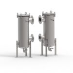
Increase filter surface area
Switching to a larger housing, adding filter elements in parallel or selecting a pleated filter element (which offers significantly more surface area than a flat one) directly reduces ΔP.
Install pre-filtration
A cyclone separator or coarse strainer upstream of the main filter element removes the bulk of solid contamination before it reaches the fine filter. This dramatically reduces the loading rate on the downstream filter, keeping pressure drop low for longer. This is one of the most effective and cost-efficient solutions in heavily contaminated applications.
Optimise the filtration micron rating
Using a coarser pre-filter to protect a finer final-stage filter (staged filtration) distributes the contamination load across multiple elements, reducing pressure drop at each stage while achieving the required final cleanliness level.
Shorten filter change or backwash intervals
In applications with high contamination loads, proactively changing filter elements or initiating backwash cycles before the maximum ΔP is reached prevents excessive pressure loss and protects downstream equipment.
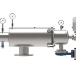
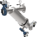
Use automatic self-cleaning filters
For continuous-process applications where stopping to change filter elements is not practical, automatic self-cleaning filters maintain consistent, low pressure drop without manual intervention.
Review system and piping design
Eliminating sharp bends, increasing pipe diameters and optimising housing inlet and outlet configurations can meaningfully reduce the overall pressure loss in a filtration system, independent of the filter element itself.
Pressure drop monitoring: why it matters
Monitoring ΔP in real time is one of the most reliable indicators of filter health and system performance. Most industrial filtration systems include a differential pressure gauge or transmitter mounted across the filter housing. When the differential pressure reaches the defined setpoint, it triggers a maintenance alert or, in automated systems, initiates a filter change or cleaning cycle.
Ignoring rising pressure drop leads to:
- Reduced flow to downstream equipment
- Increased pump energy consumption
- Risk of filter bypass or media collapse
- Unplanned downtime and emergency maintenance
A properly designed pressure drop monitoring strategy is therefore not just a technical detail; it is a cornerstone of reliable industrial filtration management.
Pressure drop in practice: industrial applications
Filter pressure drop in industrial environments varies widely depending on the sector and the fluid being processed. Some typical examples:
- Petrochemical and offshore: High-viscosity process fluids demand careful ΔP management to protect pumps and heat exchangers.
- Food and beverage: Hygienic filtration systems must balance low pressure drop with strict cleanliness standards.
- Cooling water systems: Scale, algae and particulate matter rapidly increase pressure drop if pre-filtration is inadequate.
- Wastewater and process water treatment: High contamination loads make staged filtration and regular monitoring essential.
- Chemical processing: Corrosive fluids and precise flow requirements make accurate pressure drop calculation critical at the design stage.
We are your partner in pressure drop management
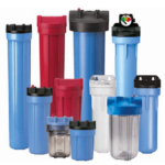
At JMF Filters, we help industrial companies select, design and supply filtration systems that deliver the right balance of cleanliness and low pressure drop. From individual filter housings to complete multi-stage filtration systems, our specialists calculate the optimal solution for your specific flow rates, fluid properties and contamination levels.
Whether you need to reduce energy costs caused by excessive pressure drop in filtration, extend filter element life or protect sensitive downstream equipment, we have the technical expertise and the product range to solve your challenge.
Get in touch with our filtration specialists today and find out how we can optimize the pressure drop performance of your filtration system.

Marc Jansen
 Expert Filtration Solutions at Your Fingertips
Seeking expert advice on oil and gas industry filters? Reach out to us for a customized solution and quote. Our team of filter specialists is ready to assist you around the clock.